
Set-up Requires Bringing Electrical Power to the Lifter and then Reviewing Some Common Points
ANVER's full line of powered vacuum generators come with a variety of electrical specifications. All important electrical information is located on the vacuum generators individual web page.
Note: All ANVER electrical components, controls and wiring follow international standards: UL, CSA, NFPA, NEC. It is the user’s responsibility to comply to all additional local electrical codes as they pertain to the installation.
Typical North American Electricity Requirements:
To be Festooned (wire loops hung from trolleys on the overhead crane) to the Lifter. Have power brought to the hoist and then down to the lifter using a retractable cable or coil cord. As you are festooning to the hoist anyway, it is just a matter of bringing additional power down to the lifter. It is best to keep the hoist and lifter pendant controls separate as they come from the factory.
Other Voltages / Phases Available:
Generators can be supplied in the following voltages by adding a transformer: 208V, 220V, 230V, 380V, 440V, 460V, 480V, 575V (consult factory for more information). All generator motors with a voltage of 120V or less use fuses or circuit breakers for protection. Motors and other devices that use more than 200V are fused and/or use thermal overload with a contactor.
Transformers should be Remote Mounted:
Increasingly many local regulations require you not to have 3 phase power running below the hook. This is usually the case with smaller units which are intended to be used by an operator. The transformer should thus be wall or remotely mounted for safety. We sell the proper transformers for our lifters which ship separately in a box and need to be installed by a qualified electrician. It is usually best to contract this to a local crane installer or electrician familiar with your state’s local code requirements.
Important: The ASME B30.20 Regulations which are the American Standard ASME website States this about “(i) Power Disconnects. (1) Hoisting Equipment using an externally powered vacuum lifter shall have a separate vacuum lifter circuit switch of the enclosed type with provision for locking, flagging, or tagging in the open (off) position. The vacuum lifter disconnect switch shall be connected on the line side (power supply side) of the hoisting equipment disconnect switch. (2) Disconnects are not required on externally powered vacuum lifters operating a 120 VAC single phase power source.”
To estimate voltage drop by wire size, material, voltage, phase, distance and amp draw, we recommend this calculator.
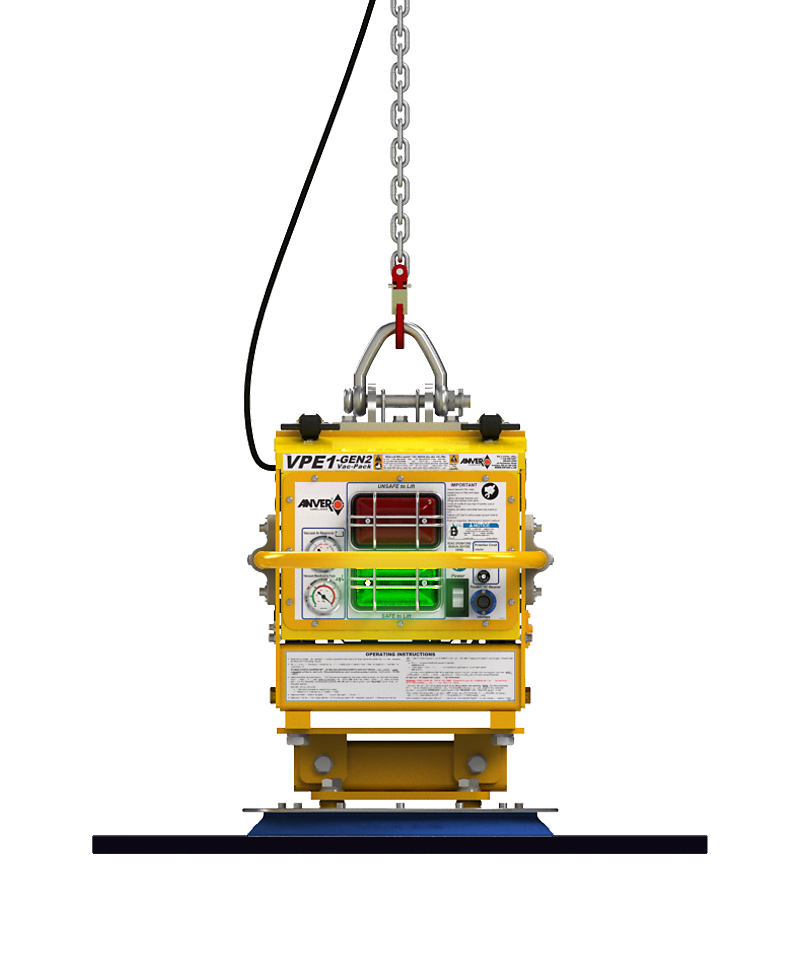
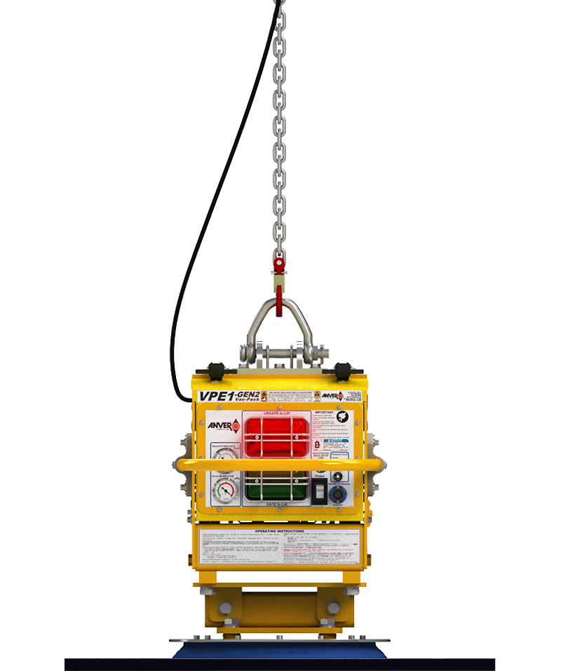
Electric Self-Cycling Operation: (ESC available on vacuum generators with Safety Lock-Out Lift Bail, VPE1-GEN3, BAE1-GEN3, VPE3-GEN3, BAE3-GEN3, GF5T, GF10T, GF15T)
The vacuum attach-and-release cycle is controlled by a switch connected to the lifting bail. When the unit is lowered onto the load and the suspension chain slackens, the full weight of the lifter is on the load, and a switch automatically starts the attachment process. Once the proper vacuum level has been achieved, a green light will illuminate letting you know it is now safe to lift. When you are ready to put the load down, lower the unit until the chain is slack, the switch will now start the release process. Once vacuum has been released you can now raise the unit with the hoist controls and you are now prepared for your next lift.

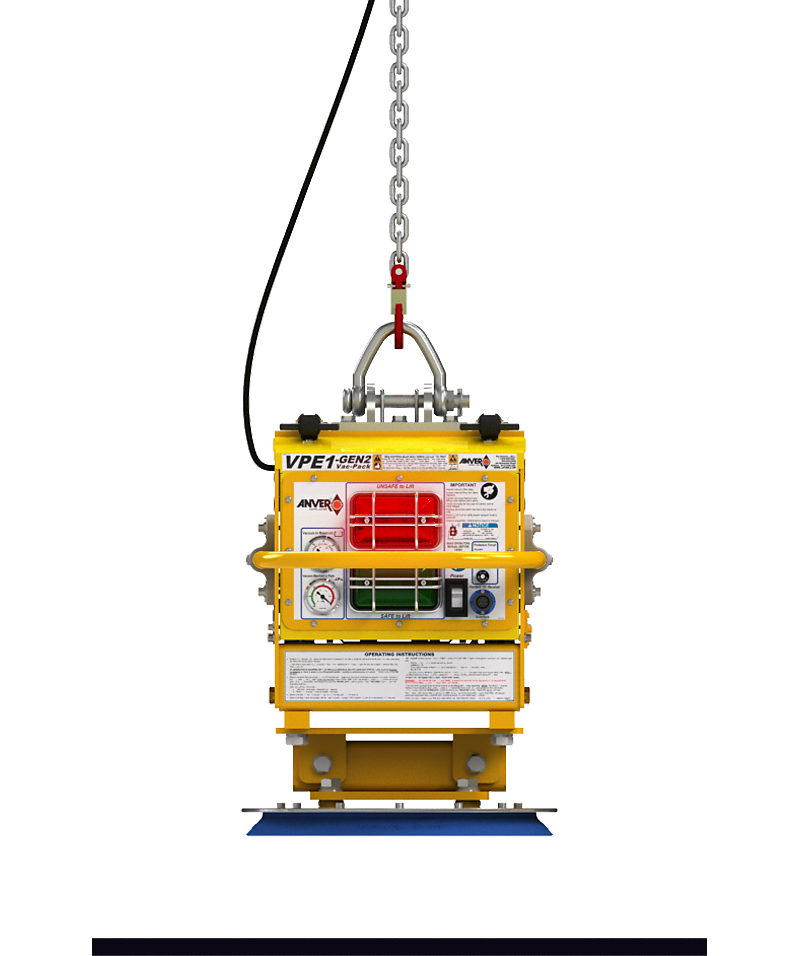
When the unit is lowered onto the load and the hoist chain slackens, the full weight of the lifter is on the load, and the internal switch automatically starts the attachment process.
When the unit is lowered onto the load and the hoist chain slackens, the full weight of the lifter is on the load, and the internal switch automatically starts the attachment process.

When the unit is lowered onto the load and the hoist chain slackens, the full weight of the lifter is on the load, and the internal switch automatically starts the attachment process.
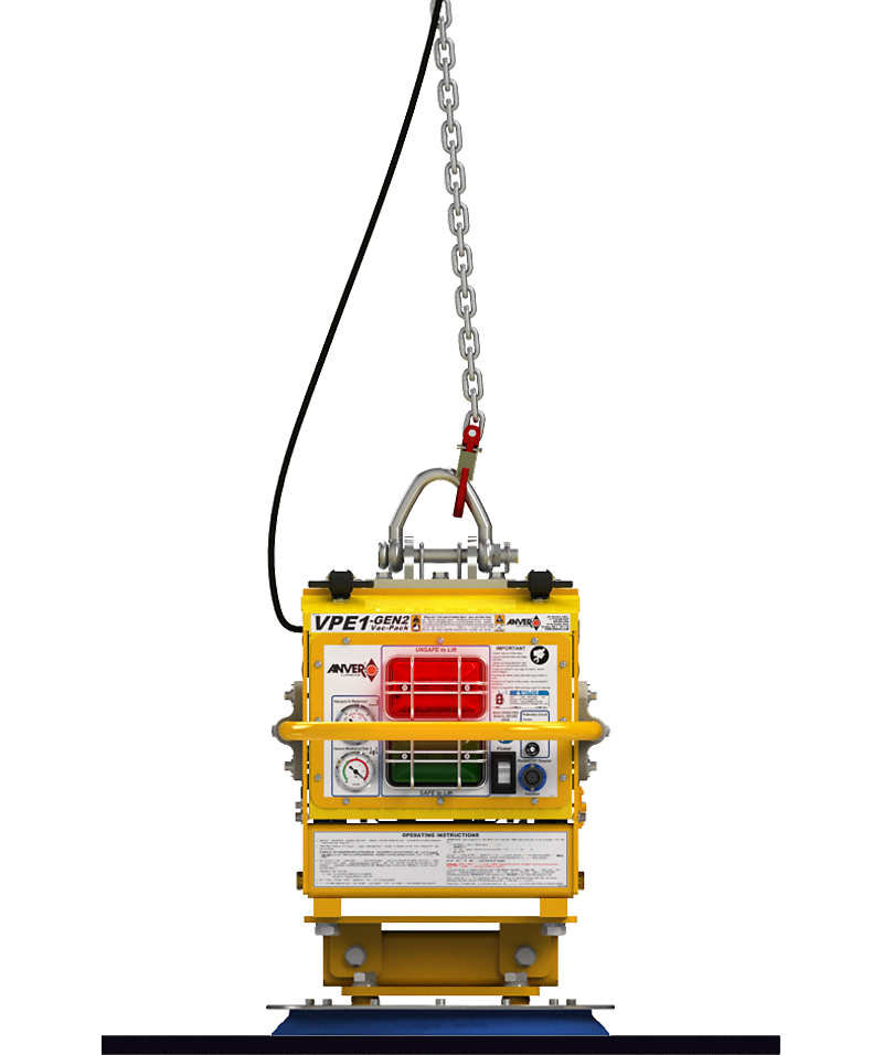
Once the proper vacuum level has been achieved, a green light will illuminate letting you know it is now safe to lift.
Once the proper vacuum level has been achieved, a green light will illuminate letting you know it is now safe to lift.

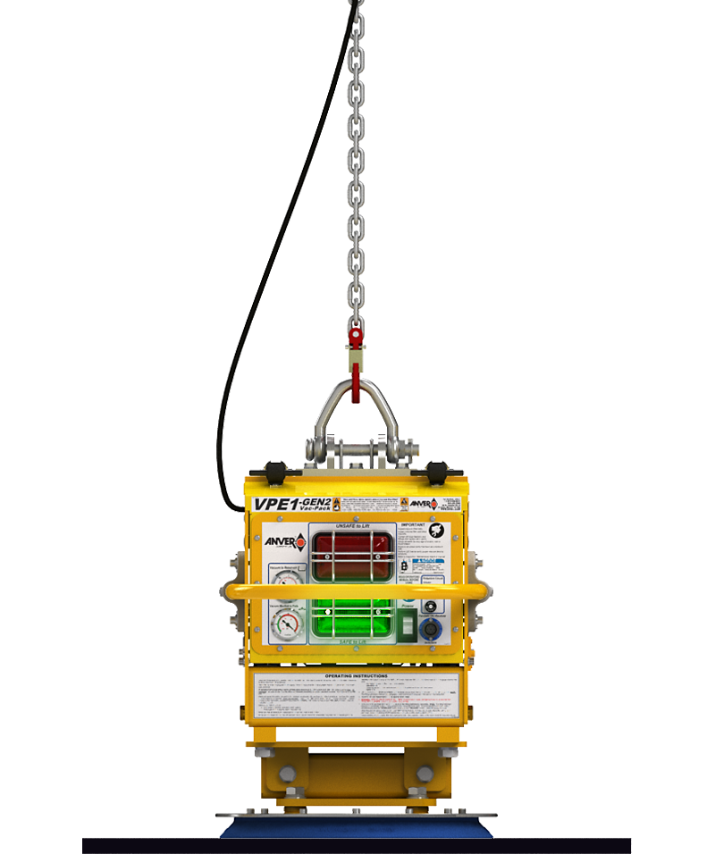
When you are ready to put the load down, lower the unit until the chain is slack to activate the switch to start the release process.

When you are ready to put the load down, lower the unit until the chain is slack to activate the switch to start the release process.
Once vacuum has been released you can now raise the unit with the hoist controls, You are now prepared for your next lift.

Once vacuum has been released you can now raise the unit with the hoist controls, You are now prepared for your next lift.
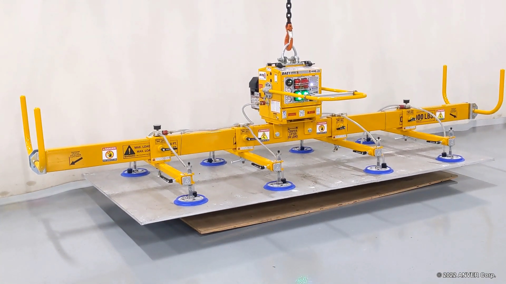
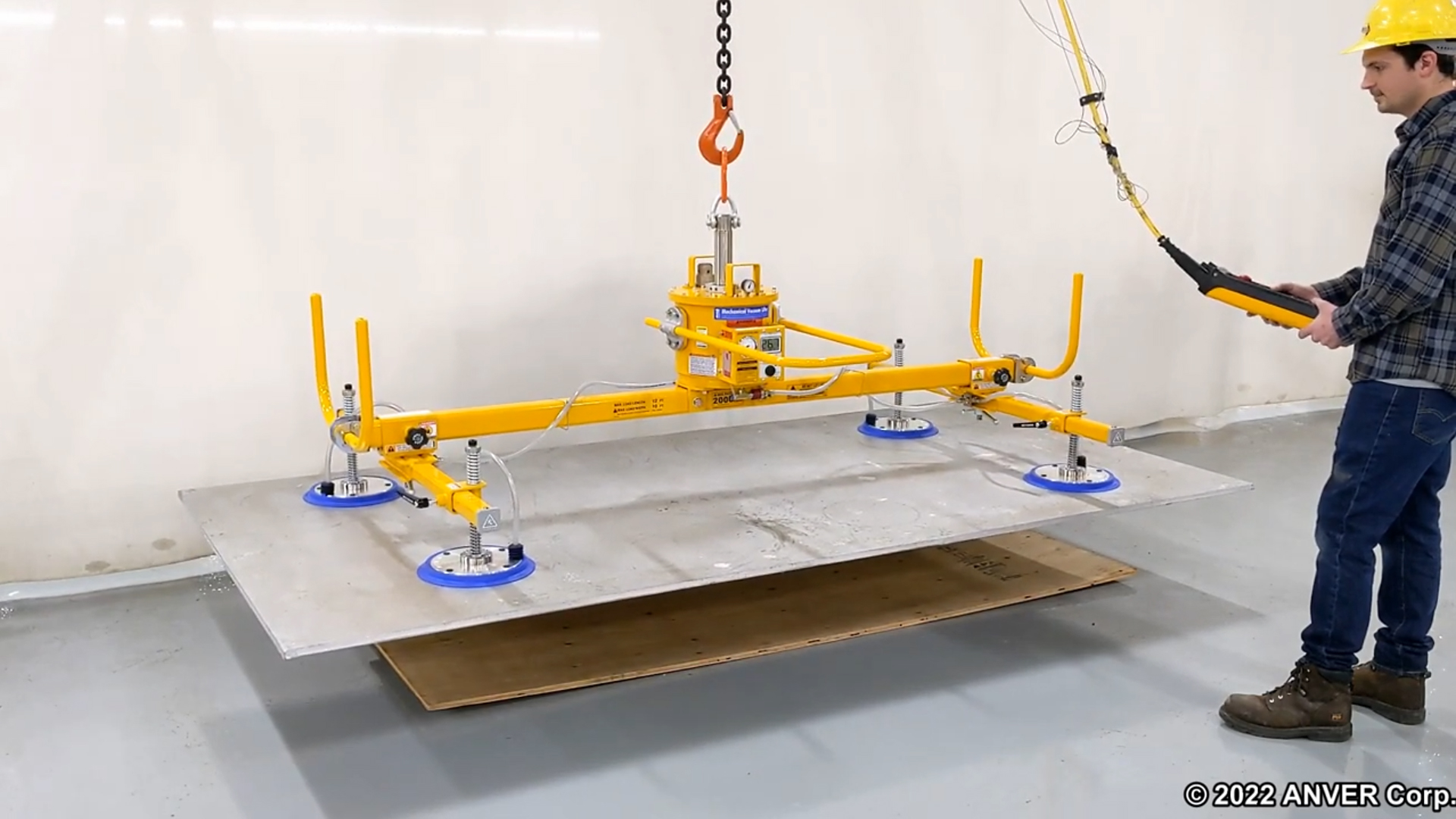
Make sure you have selected a Vacuum Lifter with adequate capacity to lift your heaviest load, and enough vacuum cups to support your longest, widest and thinnest load.
Click here to see how we calculate this.

Make sure your hoist and crane have adequate lifting capacity.
Remember, you need to deduct the vacuum lifter weight from the hoist and crane to get your overall capacity.
Check if you have adequate headroom
in your application for the lifter and
the load being lifted.
Spare and Replacement Parts
Have you ordered key spare parts such as vacuum cups or seals? While they do last, this will probably be the first item needing service.

