Selecting the Right Number of Cups for a Vacuum Lifter
For metal sheet and plate and similar fairly rigid materials
ANVER Vacuum Lifters are designed in a modular fashion. Standard components are selected to match your application. Given the vast selection and inventory that we offer, this means a lifter to match almost any application can be quickly built. ANVER designs its lifters so that each pad bears an equal load weight.
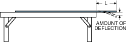
ANVER designs it’s vacuum lifters with a 2-inch deflection factor when determining the number of pads and required beam length. Based on our 30+ years experience in thousands of vacuum lifter applications, we have found that a 2-inch deflection offers an extra measure of lifting safety by reducing the curvature under the pads while at the same time making it easier to position the lifter on the load. In practice, it is difficult for operators to center a lifter using more than 2″ deflection. More information is explained on the bottom of this page.
| The following procedure is recommended for vacuum lifter selection: |
Select the Proper Beam Length, Crossarm Length and Lifting Pad Configuration
-
Identify the size of the material to be lifted
Determine the minimum and maximum dimensions and maximum weight of the load. The minimum and maximum thickness are also critical.
-
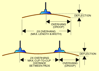
Determine the amount of allowable load overhang
Overhang (L) and spacing between pads (2L) are based on the minimum thickness of material. Click here for acceptable Steel Plate Overhang or Aluminum Plate Overhang or Glass Plate Overhang. The thinnest material to be lifted has the greatest deflection and should always be considered when determining the allowable overhang.
-
Determine the number of pads Lengthwise
Referring to the appropriate table, determine the minimum number of pads required for the maximum load length, rounding up to the next highest number. For example, if the maximum length is 120 inches and the recommended spacing between pads is 60 inches, use a lifter with a minimum of two cups (120/60=2). Determine the minimum number of lifting pads required for the maximum load length by dividing the maximum load length by 2L and rounding up to the next highest number.
-
Determine the number of pad rows
Determine the minimum number of lifting pads required for the maximum load width by dividing the maximum load width by the 2L number from the table and rounding up to the next highest number. For example, a load width of 72 inches with a recommended spacing between pads of 60 inches (72/60=1.2: rounded up to 2) requires a minimum of two pads along the width of the load.
-
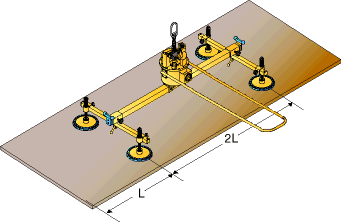
Determine the beam length
The beam length is calculated by taking 2L and adding 6 inches to it. For example, with a 2L value of 60 inches, the minimum beam length would be 66 inches (60+6). If this is not a standard length, select the next longest standard beam length.
-
Determine the Required Length of Crossarms
Subtract 2L from the maximum load width and add 6 inches. If this is not a standard length, select the next longest standard crossarm length.
-
Selecting Vacuum Lifting Pad Size and Style
Consider the following points when selecting the proper vacuum pads:
 The maximum weight to be lifted The maximum weight to be lifted
The number of pads (calculated as explained above)
The lifting surface and porosity of the load
-
Follow these guidelines for selecting vacuum pads:
Use the fewest number of pads necessary
Use pads with the largest possible diameter
The load width should never exceed five times the lifting pad width or diameter
when handling a load with a single row of pads
Pad capacities must be derated by 50% when used for vertical handling or
upending (tilting) applications
Select the proper material for the vacuum pad. Click here for Rubber Elastomer Information
|
|
Notes Regarding Deflection (Bending):
-
Brittle materials such as glass should be held nearly flat.
- For other materials such as wood, particleboard, etc., deflection can be estimated by direct measure.
NOTE: Although multiple rows may not be required when using the above guidelines, they should be considered if load tipping is a concern.
When choosing the number of crossarm members on a vacuum lifter designed for up-ending (tilting), an even number of crossarms must be specified to prevent interference with the up-ending yoke.
|
|
-
All of our standard vacuum lifters are built to order from stock using modular components, and are shipped promptly. ANVER Standard Vacuum Lifters are available in literally hundreds of possible combinations depending on the vacuum generator, beam, crossarms, and vacuum cups used. Contact one of our experienced applications engineers with your requirements so we can size the right lifter for you.
- Vacuum Lifters are shipped almost fully assembled and ready to operate. All crossarms slide up and down the beam, and also pivot to allow adjustment for narrow loads and provide for compact crating. This allows us to ship lifters with the vacuum system almost completely assembled and tested. There is little installation other than bolting on the front handle etc.
|

|


