ANVER Vacuum Cups, Vacuum Lifters, Vacuum Pumps, Vacuum Tube Lifters, Vacuum Sheet and Plate Lifters, Vacuum End-EffectorsVacuum Cups and Suction Cups
Universal Style Flat Vacuum Suction Cups
with Interchangeable Fittings

View Printer-Friendly PDF Page

Selecting a style of vacuum suction cup is determined primarily by the product to be lifted.

  • Flat Vacuum Suction Cups (listed below) are typically designed to handle flat or slightly curved surfaces. They offer fast attach/release times due to their small internal volume and are good for handling heavy, horizontal loads. Flat vacuum suction cups with cleated bottoms to prevent puckering are useful for handling flat, flexible loads such as cardboard and sheet metal.
  • Single (1.5) Bellows Vacuum Suction Cups are ideal for handling loads with uneven surfaces and irregular shapes. The bellows design compensates for product irregularities and varied heights. They have longer attach/release times than flat cups and are less suitable for lifting vertical loads.
  • Double (2.5) Bellows Vacuum Suction Cups can be used in the same applications as single bellows cups, but can accommodate greater product irregularities and height variations.  Double bellows cups are recommended only for horizontal lifting of loads.
Flat vacuum cups designed to handle flat or slightly curved surfaces

Flat vacuum cups designed to handle flat or slightly curved surfaces

Flat Vacuum Suction Cups

Flat vacuum suction cups attach quickly due to the small volume of air to be evacuated. They feature patterned knobs on the bottom to maximize capacity and are excellent for holding flat, flexible materials without deformation. Relatively stiff, the cup bodies retain their shape well in production applications. They are excellent for use on fast cycle transfer systems. Use on flat or slightly curved surfaces, and for horizontal or vertical lifting.

Flat vacuum cups designed to handle flat or slightly curved surfaces
F5 through F25
Flat vacuum cups designed to handle flat or slightly curved surfaces
F30 through F95

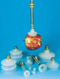
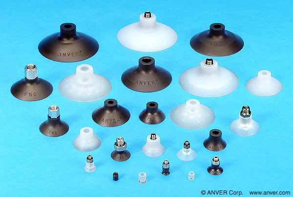
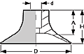
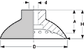
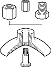
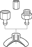
Specifications for Flat Vacuum Suction Cups:

RFQ F5-NBR

F5-NBR
Nitrile

0.21
(5.4)
0.15
(5.9)
0.35
(9.0)
0.31
(8.0)
0.002
(0.03)
0.20
(0.0)
Group 1 Fittings SLSA-1 Suspensions
SLSA-2 Suspensions
RFQ F5-SIT

F5-SIT
Silicone

0.21
(5.4)
0.15
(5.9)
0.35
(9.0)
0.31
(8.0)

0.002
(0.03)

0.20
(0.0)

Group 1 Fittings SLSA-1 Suspensions
SLSA-2 Suspensions
RFQ F10-NBR

F10-NBR
Nitrile

0.40
(10.1)
0.19
(4.7)
0.42
(10.6)
0.37
(10.6)
0.003
(0.05)
0.60
(0.3)
Group 1 Fittings SLSA-1 Suspensions
SLSA-2 Suspensions
RFQ F10-SIT

F10-SIT
Silicone

0.40
(10.1)
0.19
(4.7)
0.42
(10.6)
0.37
(10.6)

0.003
(0.05)

0.60
(0.3)

Group 1 Fittings SLSA-1 Suspensions
SLSA-2 Suspensions
RFQ F15-NBR

F15-NBR
Nitrile

0.58
(14.7)
0.19
(4.9)
0.43
(10.9)
0.36
(9.1)
0.011
(0.18)
1.40
(0.6)
Group 1 Fittings SLSA-1 Suspensions
SLSA-2 Suspensions
RFQ F15-SIT

F15-SIT
Silicone

0.58
(14.7)
0.19
(4.9)
0.43
(10.9)
0.36
(9.1)

0.011
(0.18)

1.40
(0.6)

Group 1 Fittings SLSA-1 Suspensions
SLSA-2 Suspensions
RFQ

F20-NBR
Nitrile

0.79
(20.0)
0.18
(4.5)
0.45
(11.5)
0.33
(8.5)
0.027
(0.44)
2.20
(1.0)
Group 1 Fittings SLSA-1 Suspensions
SLSA-2 Suspensions
RFQ

F20-SIT
Silicone

0.79
(20.0)
0.18
(4.5)
0.45
(11.5)
0.33
(8.5)

0.027
(0.44)

2.20
(1.0)

Group 1 Fittings SLSA-1 Suspensions
SLSA-2 Suspensions
RFQ

F25-NBR
Nitrile

0.99
(25.1)
0.15
(3.8)
0.48
(12.1)
0.38
(9.7)
0.430
(0.70)
3.10
(1.4)
Group 1 Fittings SLSA-1 Suspensions
SLSA-2 Suspensions
RFQ

F25-SIT
Silicone

0.99
(25.1)
0.15
(3.8)
0.48
(12.1)
0.38
(9.7)

0.430
(0.70)

3.10
(1.4)

Group 1 Fittings SLSA-1 Suspensions
SLSA-2 Suspensions
RFQ F30-NBR

F30-NBR
Nitrile

1.17
(29.7)
0.31
(7.8)
0.75
(19.1)
0.63
(16.0)
0.177
(2.90)
4.90
(2.2)
Group 2 Fittings SLSA-1 Suspensions
SLSA-2 Suspensions
RFQ F30-SIT

F30-SIT
Silicone

1.17
(29.7)
0.31
(7.8)
0.75
(19.1)
0.63
(16.0)

0.177
(2.90)

4.90
(2.2)

Group 2 Fittings SLSA-1 Suspensions
SLSA-2 Suspensions
RFQ F35-NBR

F35-NBR
Nitrile

1.42
(36.0)
0.31
(7.8)
0.79
(20.0)
0.63
(16.0)
0.165
(2.70)
7.00
(3.2)
Group 2 Fittings SLSA-1 Suspensions
SLSA-2 Suspensions
RFQ F35-SIT

F35-SIT
Silicone

1.42
(36.0)
0.31
(7.8)
0.79
(20.0)
0.63
(16.0)

0.165
(2.70)

7.00
(3.2)

Group 2 Fittings SLSA-1 Suspensions
SLSA-2 Suspensions
RFQ F40-NBR

F40-NBR
Nitrile

1.56
(39.6)
0.31
(7.8)
0.79
(20.0)
0.63
(16.0)
0.250
(4.00)
9.50
(4.3)
Group 2 Fittings SLSA-1 Suspensions
SLSA-2 Suspensions
RFQ F40-SIT

F40-SIT
Silicone

1.56
(39.6)
0.31
(7.8)
0.79
(20.0)
0.63
(16.0)

0.250
(4.00)

9.50
(4.3)

Group 2 Fittings SLSA-1 Suspensions
SLSA-2 Suspensions
RFQ F52-NBR

F52-NBR
Nitrile

2.05
(52.0)
0.31
(7.8)
0.87
(22.0)
0.69
(17.5)
0.427
(7.00)
15.10
(6.8)
Group 2 Fittings SLSA-1 Suspensions
SLSA-2 Suspensions
RFQ F52-SIT

F52-SIT
Silicone

2.05
(52.0)
0.31
(7.8)
0.87
(22.0)
0.69
(17.5)

0.427
(7.00)

15.10
(6.8)

Group 2 Fittings SLSA-1 Suspensions
SLSA-2 Suspensions
RFQ F60-NBR

F60-NBR
Nitrile

2.36
(60.0)
0.31
(7.9)
0.87
(22.0)
0.69
(17.5)
0.752
(12.00)
23.00
(10.4)
Group 2 Fittings SLSA-1 Suspensions
SLSA-2 Suspensions
RFQ F60-SIT

F60-SIT
Silicone

2.36
(60.0)
0.31
(7.9)
0.87
(22.0)
0.69
(17.5)

0.752
(12.00)

23.00
(10.4)

Group 2 Fittings SLSA-1 Suspensions
SLSA-2 Suspensions
RFQ F77-NBR

F77-NBR
Nitrile

2.94
(74.7)
0.46
(11.7)
1.24
(31.5)
1.02
(26.0)
0.976
(16.00)
36.20
(16.4)
Group 3 Fittings SLSA-2 Suspensions
RFQ F77-SIT

F77-SIT
Silicone

2.94
(74.7)
0.46
(11.7)
1.24
(31.5)
1.02
(26.0)

0.976
(16.00)

36.20
(16.4)

Group 3 Fittings SLSA-2 Suspensions
RFQ F85-NBR
Nitrile
3.30
(85.0)
0.48
(12.0)
1.20
(31.0)
1.00
(26.0)
1.85
(30.32)
39.00
(17.8)
Group 3 Fittings SLSA-2 Suspensions
RFQ F85-SIT
Silicone
3.30
(85.0)
0.48
(12.0)
1.20
(31.0)
1.00
(26.0)
1.85
(30.32)
39.00
(17.8)
Group 3 Fittings SLSA-2 Suspensions
RFQ F95-NBR

F95-NBR
Nitrile

3.74
(95.0)
0.47
(12.0)
1.46
(37.0)
1.02
(26.0)
2.899
(47.50)
42.30
(19.2)
Group 3 Fittings SLSA-2 Suspensions

RFQ

F95-SIT

F95-SIT
Silicone

3.74
(95.0)
0.47
(12.0)
1.46
(37.0)
1.02
(26.0)

2.899
(47.50)

42.30
(19.2)

Group 3 Fittings SLSA-2 Suspensions
Group 1 Series Vacuum fittings
Group 1 Fittings
Group 2 Series Vacuum fittings
Group 2 Fittings
Group 3 Series Vacuum fittings
Group 3 Fittings
Group 1 Fittings Group 2 Fittings Group 3 Fittings

Notes: 

  • Click on the small thumbnail photo to enlarge for more detail and specifications.
  •  * The cup capacities shown above are based on 24″Hg at sea level with a safety factor of two (2). This is the US ANSI ASME Standard B30.20 for vacuum lifter specifications and is commonly used in North America as a design capacity for vacuum components. When using in vertical applications, take these values and divide again by 2 to obtain a 4 to 1 safety factor per the ANSI specifications. These are realistic working capacities when designing equipment.
  • Other manufacturers use a pull-off figure at 27″Hg to show a high capacity value for their cups.  This is accurate, but requires users to do all the math themselves to build in safety factors. The values are basically the same, but it is necessary to calculate the working capacities with a safety factor via the following formula at sea level:

Pull-off value (at 27″Hg) = ANVER’s Listed Capacity x 2 x 1.125 (at 24″Hg)
                                 

  • For example: ANVER vacuum cup number F52 has a rated capacity of 15.10 lb at 24″Hg.  The pull-off capacity at 27″Hg for this cup would be 15.10 x 2 x 1.25 = 33.79 lbs.  From this point, it is necessary to calculate the safety factor based on the vacuum level being used, and the altitude.