
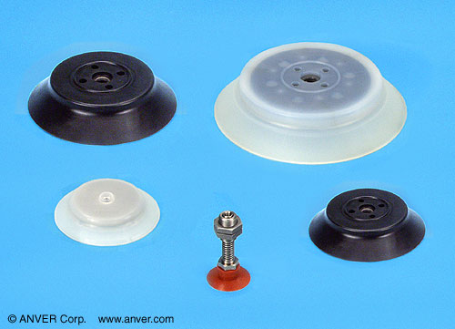
Vacuum Cups and Suction Cups
ANVER C-F Flat Vacuum Cups
|
|
Features
Applications
|
Specifications for Vacuum Suction Cups
 |
|||||||||||||||
|
|
 |
Product Photo (Click to Enlarge) |
Vacuum Cup No. |
øA in. (mm) |
øB in. (mm) |
øC in. (mm) |
øD in. (mm) |
E Static Height in. (mm) |
F in. (mm) |
G in. (mm) |
H in. (mm) |
øJ in. (mm) |
Horizontal Load Capacity* at 24 in. Hg (609.6mm Hg) [2:1 Safety Factor] lb (kg) |
Recommended Fitting (Click Image For More Info) |
Suspension Group For Cups (Click Image For More Info) |
 |
C-F2-NBR (Nitrile) C-PFG2-NBR PFG-2A-NBR |
0.08 (2) |
0.08 (2) |
0.05 (1.2) |
0.16 (4) |
0.16 (4) |
0.02 (0.5) |
0.10 (2.5) |
0.06 (1.5) |
0.12 (3) |
11 grams |
 |
 |
||
 |
C-F2-SIT (Translucent Silicone) C-PFG2-SIT PFG-2A-SI 3187 |
0.08 (2) |
0.08 (2) |
0.05 (1.2) |
0.16 (4) |
0.16 (4) |
0.02 (0.5) |
0.10 (2.5) |
0.06 (1.5) |
0.12 (3) |
11 grams |
|
|
||
 |
C-F3.5A-NBR (Nitrile) C-PFG3.5A-NBR PFG-3.5A-NBR |
0.14 (3.5) |
0.08 (2) |
0.05 (1.2) |
0.16 (4) |
0.16 (4) |
0.02 (0.5) |
0.10 (2.5) |
0.06 (1.5) |
0.12 (3) |
33 grams |
|
|
||
 |
C-F3.5A-SIT (Translucent Silicone) C-PFG3.5A-SIT PFG-3.5A-SI 3190 |
0.14 (3.5) |
0.08 (2) |
0.05 (1.2) |
0.16 (4) |
0.16 (4) |
0.02 (0.5) |
0.10 (2.5) |
0.06 (1.5) |
0.12 (3) |
33 grams |
|
|
||
 |
C-F3.5A-FPM (Viton®) C-PFG3.5A-FPM PFG-3.5A-FKM |
0.14 (3.5) |
0.08 (2) |
0.05 (1.2) |
0.16 (4) |
0.16 (4) |
0.02 (0.5) |
0.10 (2.5) |
0.06 (1.5) |
0.12 (3) |
33 grams |
|
|
||
 |
|||||||||||||||
|
|
|
Product Photo (Click to Enlarge) |
Vacuum Cup No. |
øA in. (mm) |
øB in. (mm) |
øC in. (mm) |
øD in. (mm) |
E Static Height in. (mm) |
F in. (mm) |
G in. (mm) |
H in. (mm) |
øJ in. (mm) |
Horizontal Load Capacity* at 24 in. Hg (609.6mm Hg) [2:1 Safety Factor] lb (kg) |
Recommended Fitting (Click Image For More Info) |
Suspension Group For Cups (Click Image For More Info) |
 |
C-F5-NBR (Nitrile) C-PFG5-NBR PFG-5A-NBR |
0.20 (5) |
0.16 (4) |
0.06 (1.4) |
0.30 (7.5) |
0.26 (6.5) |
0.03 (0.8) |
0.16 (4) |
0.08 (2) |
0.24 (6) |
67 grams |
|
|
||
 |
C-F5-SIT (Translucent Silicone) C-PFG5-SIT PFG-5A-SI 3193 |
0.20 (5) |
0.16 (4) |
0.06 (1.4) |
0.30 (7.5) |
0.26 (6.5) |
0.03 (0.8) |
0.16 (4) |
0.08 (2) |
0.24 (6) |
67 grams |
 |
|
||
 |
C-F6-NBR (Nitrile) C-PFG6-NBR PFG-6A-NBR |
0.24 (6) |
0.16 (4) |
0.08 (2) |
0.30 (7.5) |
0.26 (6.5) |
0.03 (0.8) |
0.16 (4) |
0.08 (2) |
0.24 (6) |
97 grams |
|
|
||
 |
C-F6-SIT (Translucent Silicone) C-PFG6-SIT PFG-6A-SI |
0.24 (6) |
0.16 (4) |
0.08 (2) |
0.30 (7.5) |
0.26 (6.5) |
0.03 (0.8) |
0.16 (4) |
0.08 (2) |
0.24 (6) |
97 grams |
|
|
||
| – | Product Photo | Part No. | A | B | C | D | E | F | G | H | J | – | Fitting | Suspension | |
 |
C-F8-NBR (Nitrile) C-PFG8-NBR PFG-8A-NBR |
0.31 (8) |
0.16 (4) |
0.08 (2) |
0.31 (8) |
0.28 (7) |
0.05 (1.2) |
0.16 (4) |
0.08 (2) |
0.24 (6) |
161 grams |
|
|
||
 |
C-F8-SIT (Translucent Silicone) C-PFG8-SIT PFG-8A-SI 3196 |
0.31 (8) |
0.16 (4) |
0.08 (2) |
0.31 (8) |
0.28 (7) |
0.05 (1.2) |
0.16 (4) |
0.08 (2) |
0.24 (6) |
161 grams |
|
|
||
 |
C-F8-PUR (Polyurethane) C-PFG8-PUR PFG-8A-U |
0.31 (8) |
0.16 (4) |
0.08 (2) |
0.31 (8) |
0.28 (7) |
0.05 (1.2) |
0.16 (4) |
0.08 (2) |
0.24 (6) |
161 grams |
|
|
||
 |
C-F10-NBR (Nitrile) C-PFG10-NBR PFG-10A-NBR |
0.39 (10) |
0.16 (4) |
0.08 (2) |
0.33 (8.5) |
0.30 (7.5) |
0.06 (1.5) |
0.16 (4) |
0.08 (2) |
0.24 (6) |
256 grams |
|
|
||
| – | Product Photo | Part No. | A | B | C | D | E | F | G | H | J | – | Fitting | Suspension | |
 |
C-F10-SIT (Translucent Silicone) C-PFG10-SIT PFG-10A-SI 3200 |
0.39 (10) |
0.16 (4) |
0.08 (2) |
0.33 (8.5) |
0.30 (7.5) |
0.06 (1.5) |
0.16 (4) |
0.08 (2) |
0.24 (6) |
256 grams |
|
|
||
 |
C-F10-PUR (Polyurethane) C-PFG10-PUR PFG-10A-U |
0.39 (10) |
0.16 (4) |
0.08 (2) |
0.33 (8.5) |
0.30 (7.5) |
0.06 (1.5) |
0.16 (4) |
0.08 (2) |
0.24 (6) |
256 grams |
|
|
||
 |
C-F10-FPM (Viton®) C-PFG10-FPM PFG-10A-FKM |
0.39 (10) |
0.16 (4) |
0.08 (2) |
0.33 (8.5) |
0.30 (7.5) |
0.06 (1.5) |
0.16 (4) |
0.08 (2) |
0.24 (6) |
256 grams |
|
|
||
|
|
 |
C-F15-NBR (Nitrile) C-PFG15-NBR PFG-15-NBR PFG-15A-NBR |
0.62 (15.7) |
0.18 (4.5) |
N/A | 0.47 (12) |
0.31 (8) |
0.079 (2) |
0.14 (3.5) |
N/A | 0.31 (8) |
1.29 (0.58) |
|
|
|
| – | Product Photo | Part No. | A | B | C | D | E | F | G | H | J | – | Fitting | Suspension | |
|
|
 |
C-F15-SIT (Translucent Silicone) C-PFG15-SIT PFG-15-SI PFG-15A-SI 3204 |
0.62 (15.7) |
0.18 (4.5) |
N/A | 0.47 (12) |
0.31 (8) |
0.079 (2) |
0.14 (3.5) |
N/A | 0.31 (8) |
1.29 (0.58) |
|
|
|
|
|
 |
C-F15-NM (NOMATHANE®) |
0.62 (15.7) |
0.18 (4.5) |
N/A | 0.47 (12) |
0.31 (8) |
0.079 (2) |
0.14 (3.5) |
N/A | 0.31 (8) |
1.29 (0.58) |
|
|
|
 |
|||||||||||||
|
|
|
Product Photo (Click to Enlarge) |
Vacuum Cup No. |
øA in. (mm) |
øB in. (mm) |
øC in. (mm) |
øD in. (mm) |
E Static Height in. (mm) |
F in. (mm) |
H in. (mm) |
Horizontal Load Capacity* at 24 in. Hg (609.6mm Hg) [2:1 Safety Factor] lb (kg) |
Adapter Fitting for Suspension (Click on Image for More Info) |
SLSA1 Series Suspension (Click on Image for More Info) |
|
|
 |
C-F20-NBR (Nitrile) C-PFG20-NBR PFG-20-NBR PFG-20B-NBR |
0.82 (20.9) |
0.22 (5.5) |
0.43 (11) |
0.59 (15) |
0.39 (10) |
0.085 (2.17) |
0.18 (4.6) |
2.31 (1.05) |
 |
|
|
|
|
 |
C-F20-SIT (Translucent Silicone) C-PFG20-SIT PFG-20-SI PFG-20B-SI 3207 |
0.82 (20.9) |
0.22 (5.5) |
0.43 (11) |
0.59 (15) |
0.39 (10) |
0.085 (2.17) |
0.18 (4.6) |
2.31 (1.05) |
|
|
|
|
|
 |
C-F20-NM (NOMATHANE®) |
0.82 (20.9) |
0.22 (5.5) |
0.43 (11) |
0.59 (15) |
0.39 (10) |
0.085 (2.17) |
0.18 (4.6) |
2.31 (1.05) |
|
|
|
 |
C-F30-NBR (Nitrile) C-PFG30-NBR PFG-30-NBR |
1.18 (30) |
0.24 (6) |
0.43 (11) |
0.55 (14) |
0.47 (12) |
0.08 (2) |
0.28 (7) |
– | |
|
||
| – | Product Photo | Part No. | A | B | C | D | E | F | H | Adapter | Suspension | ||
 |
C-F30-SIT (Translucent Silicone) C-PFG30-SIT PFG-30-SI 3215 |
1.18 (30) |
0.24 (6) |
0.43 (11) |
0.55 (14) |
0.47 (12) |
0.08 (2) |
0.28 (7) |
– | |
|
||
 |
C-F35-NBR (Nitrile) C-PFG35-NBR PFG-35-NBR |
1.38 (35) |
0.24 (6) |
0.43 (11) |
0.83 (21) |
0.55 (14) |
0.12 (3) |
0.28 (7) |
– | |
|
||
 |
C-F35-SIT (Translucent Silicone) C-PFG35-SIT PFG-35-SI |
1.38 (35) |
0.24 (6) |
0.43 (11) |
0.83 (21) |
0.55 (14) |
0.12 (3) |
0.28 (7) |
– | |
|
||
 |
C-F40-NBR (Nitrile) C-PFG40-NBR PFG-40-NBR |
1.57 (40) |
0.24 (6) |
0.43 (11) |
0.94 (24) |
0.55 (14) |
0.16 (4) |
0.28 (7) |
– | |
|
||
 |
C-F40-SIT (Translucent Silicone) C-PFG40-SIT PFG-40-SI 3219 |
1.57 (40) |
0.24 (6) |
0.43 (11) |
0.94 (24) |
0.55 (14) |
0.16 (4) |
0.28 (7) |
– | |
|
||
 |
|||||||||||||
|
|
|
Product Photo (Click to Enlarge) |
Vacuum Cup No. |
øA in. (mm) |
øB in. (mm) |
øC in. (mm) |
øD in. (mm) |
E Static Height in. (mm) |
F in. (mm) |
H in. (mm) |
Adapter Fitting for Suspension (Click on Image for More Info) |
‘Top of Cup’ Adapter Fitting for Suspension (Click on Image for More Info) |
Suspension Group For Cups (Click Image For More Info) |
 |
C-F50-NBR (Nitrile) C-PFG50-NBR PFG-50-NBR |
1.97 (50) |
0.31 (8) |
0.79 (20) |
1.06 (27) |
0.59 (15) |
0.14 (3.5) |
0.28 (7) |
 |
 |
 |
||
 |
C-F50-SIT (Translucent Silicone) C-PFG50-SIT PFG-50-SI 3223 |
1.97 (50) |
0.31 (8) |
0.79 (20) |
1.06 (27) |
0.59 (15) |
0.14 (3.5) |
0.28 (7) |
|
|
|
||
|
|
|
|
Product Photo (Click to Enlarge) |
Vacuum Cup No. |
øA in. (mm) |
øB | øD in. (mm) |
E Static Height in. (mm) |
F in. (mm) |
H in. (mm) |
Adapter Fitting for Suspension (Click on Image for More Info) |
SLSA3 Series Suspension (Click on Image for Larger Image; More Info) |
 |
C-F60-NBR-M10 (Nitrile) C-PFG60-NBR-M10 PFG-60-NBR |
2.36 (60) |
M10 x 1.25 |
0.69 (17.5) |
0.73 (18.5) |
0.20 (5) |
0.10 (2.5) |
N/A | N/A | ||
 |
C-F60-SIT-M10 (Translucent Silicone) C-PFG60-SIT-M10 PFG-60-SI 3227 |
2.36 (60) |
M10 x 1.25 |
0.69 (17.5) |
0.73 (18.5) |
0.20 (5) |
0.10 (2.5) |
N/A | N/A | ||
 |
C-F60-PUR-M10 (Polyurethane) C-PFG60-PUR-M10 |
2.36 (60) |
M10 x 1.25 |
0.69 (17.5) |
0.73 (18.5) |
0.20 (5) |
0.10 (2.5) |
N/A | N/A | ||
 |
C-F60-NBR-G14 (Nitrile) C-PFG60-NBR-G14 |
2.36 (60) |
G1/4″ female |
0.69 (17.5) |
0.61 (15.5) |
0.20 (5) |
– |  |
 |
||
| – | Product Photo | Part No. | A | B | D | E | F | H | Adapter | Suspension | |
 |
C-F60-SIT-G14 (Translucent Silicone) C-PFG60-SIT-G14 |
2.36 (60) |
G1/4″ female |
0.69 (17.5) |
0.61 (15.5) |
0.20 (5) |
– | |
|
||
 |
C-F60-PUR-G14 (Polyurethane) C-PFG60-PUR-G14 |
2.36 (60) |
G1/4″ female |
0.69 (17.5) |
0.61 (15.5) |
0.20 (5) |
– | |
|
||
 |
C-F80-NBR-M10 (Nitrile) C-PFG80-NBR-M10 PFG-80-NBR |
3.15 (80) |
M10 x 1.25 |
0.69 (17.5) |
0.81 (20.5) |
0.24 (6) |
0.10 (2.5) |
N/A | N/A | ||
 |
C-F80-SIT-M10 (Translucent Silicone) C-PFG80-SIT-M10 PFG-80-SI 3230 |
3.15 (80) |
M10 x 1.25 |
0.69 (17.5) |
0.81 (20.5) |
0.24 (6) |
0.10 (2.5) |
N/A | N/A | ||
| – | Product Photo | Part No. | A | B | D | E | F | H | Adapter | Suspension | |
 |
C-F80-NBR-G14 (Nitrile) C-PFG80-NBR-G14 |
3.15 (80) |
G1/4″ female |
0.69 (17.5) |
0.67 (17) |
0.24 (6) |
– | |
|
||
 |
C-F80-SIT-G14 (Translucent Silicone) C-PFG80-SIT-G14 |
3.15 (80) |
G1/4″ female |
0.69 (17.5) |
0.67 (17) |
0.24 (6) |
– | |
|
||
 |
C-F95-NBR-M10 (Nitrile) C-PFG95-NBR-M10 PFG-95-NBR |
3.74 (95) |
M10 x 1.25 |
0.69 (17.5) |
0.83 (21) |
0.24 (6) |
0.10 (2.5) |
N/A | N/A | ||
 |
C-F95-SIT-M10 (Translucent Silicone) C-PFG95-SIT-M10 PFG-95-SI 3233 |
3.74 (95) |
M10 x 1.25 |
0.69 (17.5) |
0.83 (21) |
0.24 (6) |
0.10 (2.5) |
N/A | N/A | ||
| – | Product Photo | Part No. | A | B | D | E | F | H | Adapter | Suspension | |
 |
C-F95-NBR-G14 (Nitrile) C-PFG95-NBR-G14 |
3.74 (95) |
G1/4″ female |
0.69 (17.5) |
0.71 (18) |
0.24 (6) |
– | |
|
||
 |
C-F95-SIT-G14 (Translucent Silicone) C-PFG95-SIT-G14 |
3.74 (95) |
G1/4″ female |
0.69 (17.5) |
0.71 (18) |
0.24 (6) |
– | |
|
|
|
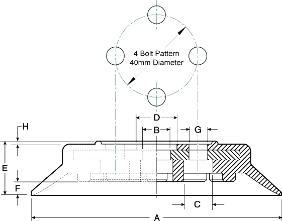
Product Photo (Click to Enlarge) |
Vacuum Cup No. |
øA in. (mm) |
øB in. (mm) |
øC in. (mm) |
øD in. (mm) |
E Static Height in. (mm) |
F in. (mm) |
G in. (mm) |
H in. (mm) |
 |
C-F120-NBR (Nitrile) C-PFG120-NBR PFG-120-NBR |
4.72 (120) |
0.55 (14) |
0.55 (14) |
0.79 (20) |
1.00 (25.4) |
0.24 (6) |
4 x ø8.7 x ø40 | 0.59 (1.5) |
|
 |
C-F120-SIT (Translucent Silicone) C-PFG120-SIT PFG-120-SI |
4.72 (120) |
0.55 (14) |
0.55 (14) |
0.79 (20) |
1.00 (25.4) |
0.24 (6) |
4 x ø8.7 x ø40 | 0.59 (1.5) |
|
 |
C-F150-NBR (Nitrile) C-PFG150-NBR PFG-150-NBR |
5.91 (150) |
0.51 (13) |
0.55 (14) |
0.79 (20) |
1.28 (32.5) |
0.35 (9) |
4 x ø8.7 x ø40 | 0.59 (1.5) |
|
| – | Product Photo | Part No. | A | B | C | D | E | F | G | H |
 |
C-F150-SIT (Translucent Silicone) C-PFG150-SIT PFG-150-SI |
5.91 (150) |
0.51 (13) |
0.55 (14) |
0.79 (20) |
1.28 (32.5) |
0.35 (9) |
4 x ø8.7 x ø40 | 0.59 (1.5) |
|
 |
C-F200-NBR (Nitrile) C-PFG200-NBR PFG-200-NBR |
7.87 (200) |
0.51 (13) |
0.47 (12) |
0.79 (20) |
1.48 (37.5) |
0.51 (13) |
4 x ø8.7 x ø40 | 0.59 (1.5) |
|
 |
C-F200-SIT (Translucent Silicone) C-PFG200-SIT PFG-200-SI |
7.87 (200) |
0.51 (13) |
0.47 (12) |
0.79 (20) |
1.48 (37.5) |
0.51 (13) |
4 x ø8.7 x ø40 | 0.59 (1.5) |
Notes:
-
The cup capacities shown above ( * ) are theoretical capacities based on 24″Hg at sea level with a safety factor of two (2) and a ± 5% margin of error. This is the US ANSI ASME Standard B30.20 for vacuum lifter specifications and is commonly used in North America as a design capacity for vacuum components. When used in vertical applications, take these values and divide again by 2 to obtain a 4 to 1 safety factor per the ANSI specifications. These are realistic working capacities when designing equipment.
-
Other manufacturers use a pull-off figure at 27″Hg to show a high capacity value for their cups. This is accurate, but requires users to do all the math themselves to build in safety factors. The values are basically the same, but it is necessary to calculate the working capacities with a safety factor via the following formula at sea level:
Pull-off value (at 27″Hg) = ANVER’s Listed Capacity x 2 x 1.125 (at 24″Hg)
-
For example: ANVER vacuum cup number F52 has a rated capacity of 15.10 lb at 24″Hg. The pull-off capacity at 27″Hg for this cup would be 15.10 x 2 x 1.25 = 33.79 lbs. From this point, it is necessary to calculate the safety factor based on the vacuum level being used, and the altitude.
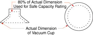
-
To ensure safety, 80% of actual overall diameter is used when determining Load Capacity.
| |
|
Viton® is a registered trademark of DuPont Dow Elastomers


