
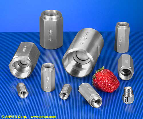
Check Valves for Vacuum Systems
New and Improved Check Valves by ANVER – One Piece Casing for Leak Proof Construction
Competitively priced and used in virtually every vacuum application shown on our website
![]()
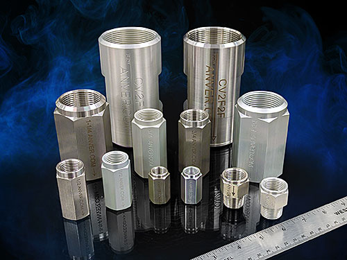 |
These high-quality Check Valves are specially manufactured in the U.S.A. by ANVER, for ANVER lifting systems. Versatile, one-way Check Valves work with nearly all of ANVER’s vacuum applications where vacuum loss prevention is required. ANVER Check Valves can operate in any position with the highest flow available making them the best overall value for mid-range vacuum level systems in the industry. Features
Specifications
Tips
|
 |
Product Photo |
Part |
Pipe |
Height |
Hex Size |
Item Weight oz. (grams) |
Cracking Pressure* |
Flow Rate |
Flow Rate (Approx. SCFM)** |
||
| in. Hg (kPa) |
PSI ± 0.14 [Unless Specified] |
||||||||||
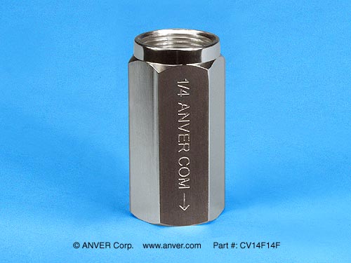 |
CV14F14F Aluminum |
1/4″ NPT (Female) x 1/4″ NPT (Female) |
1.38 (35) |
.709 (18) |
0.688 (19.5) |
0.58 (-1.96) |
0.28 | 1.15 | 8.22 | ||
| |
CV14F14FSS Stainless Steel (Special Order) |
1/4″ NPT (Female) x 1/4″ NPT (Female) |
1.38 (35) |
.709 (18) |
1.958 (55.5) |
0.58 (-1.96) |
0.28 | 1.15 | 8.22 | ||
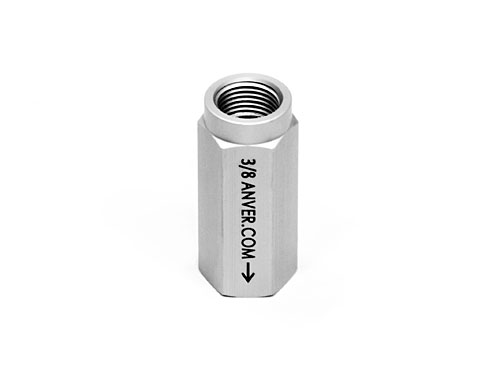 |
CV38F38F Aluminum |
3/8″ NPT (Female) x 3/8″ NPT (Female) |
2.13 (54) |
1.00 (25.4) |
1.340 (38) |
0.60 (-2.03) |
0.30 | 4.7 | 33.63 | ||
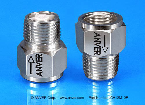 |
CV12M12F Aluminum |
1/2″ NPT (Male) x 1/2″ NPT (Female) |
1.38 (35) |
1.00 (25.4) |
0.776 (22) |
0.60 (-2.03) |
0.30 | 4.7 | 33.63 | ||
| |
CV12M12FSS Stainless Steel (Special Order) |
1/2″ NPT (Male) x 1/2″ NPT (Female) |
1.38 (35) |
1.00 (25.4) |
2.081 (59) |
0.60 (-2.03) |
0.30 | 4.7 | 33.63 | ||
| |
CV12M12F-G Aluminum |
1/2″ G (Male) x 1/2″ G (Female) |
1.38 (35) |
1.06 (27) |
1.023 (29) |
0.60 (-2.03) |
0.30 | 4.7 | 33.63 | ||
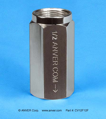 |
CV12F12F Aluminum |
1/2” NPT (Female) x 1/2” NPT (Female) |
2.13 (54) |
1.00 (25.4) |
1.534 (43.5) |
0.60 (-2.03) |
0.30 | 4.7 | 33.63 | ||
| |
CV12F12FSS Stainless Steel (Special Order |
1/2” NPT (Female) x 1/2” NPT (Female) |
2.13 (54) |
1.00 (25.4) |
4.445 (126) |
0.60 (-2.03) |
0.30 | 4.7 | 33.63 | ||
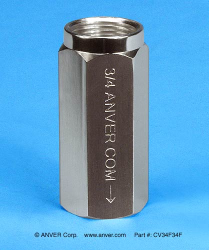 |
CV34F34F Aluminum |
3/4″ NPT (Female) x 3/4″ NPT (Female) |
2.75 (70) |
1.18 (30) |
2.575 (73) |
0.52 (-1.76) |
0.26 | 10.8 | 77.27 | ||
| |
CV34F34FSS Stainless Steel (Special Order) |
3/4″ NPT (Female) x 3/4″ NPT (Female) |
2.75 (70) |
1.18 (30) |
7.143 (203) |
0.52 (-1.76) |
0.26 | 10.8 | 77.27 | ||
 |
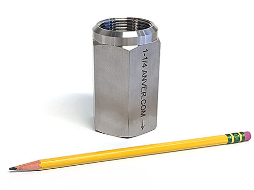
CV114F114F Aluminum |
1 1/4″ NPT (Female) x 1 1/4″ NPT (Female) |
3.38 (85.9) |
2.00 (51.8) |
9.453 (268) |
0.14 (-0.47) |
0.07 +0.14/-0.05 | 28 | 200.33 | ||
 |
CV114F114FSS Stainless Steel (Special Order) |
1 1/4″ NPT (Female) x 1 1/4″ NPT (Female) |
3.38 (85.9) |
2.00 (51.8) |
26.332 (747) |
0.14 (-0.47) |
0.07 +0.14/-0.05 | 28 | 200.33 | ||
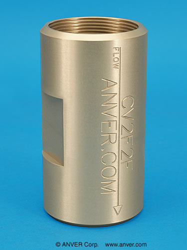 |
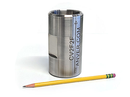
CV2F2F Aluminum |
2″ NPT (Female) x 2″ NPT (Female) |
5.00 (127.0) |
– | 19.330 (548) |
0.35 (-1.19) |
0.17 | 63 | 450.75 | ||
 |
CV2F2FSS Stainless Steel (Special Order) |
2″ NPT (Female) x 2″ NPT (Female) |
5.00 (127.0) |
– | 52.735 (1495) |
0.35 (-1.19) |
0.17 | 63 | 450.75 | ||
Note: These check valves were specifically designed and built for ANVER’s vacuum lifting systems, and have been proven in actual vacuum system installations. Ordinary check valves designed for compressed air systems are unsuitable for use in vacuum systems and can adversely affect your system.
*Cracking Pressure refers to the minimum pressure differential needed between the inlet and outlet of the valve to lift the plunger off its seat to generate flow.
**Flow Coefficient {Cv} is determined by the flow of water through a valve at 60°F in US gallon/minute at a pressure drop of 1 lb./in2. Cv is a relative value that allows comparison between different valves. The actual flow rate in SCFM is dependent on other variables within the application. Since water is a non-compressible liquid and air is a compressible gas, the inlet and outlet pressure are needed to determine actual flow of air since the density of air changes with pressure.
General equation for air flow when Cv is known is:
SCFM = (Cv x (∆P x ((Pin-∆P) + 14.7))1/2) ÷ 1.024
Where Pin = Inlet Pressure & ∆P = Pressure Differential
Flow rates shown are based on the formula for air flow to atmosphere calculated by:
SCFM = Cv x ((((PSIG+14.7) x 0.46) x ((PSIG+14.7)*0.54))1/2 ÷ 1.024
Where gauge pressure, PSIG, is assumed to be negligible.
![]()
13600241A


